My job is to design something cool in the shortest amount of time. The machine will need to be robust, simple, and easily comprehended by me. The mechanics and the code will have to be as easy as possible, so I can reduce the time I would need to troubleshoot.
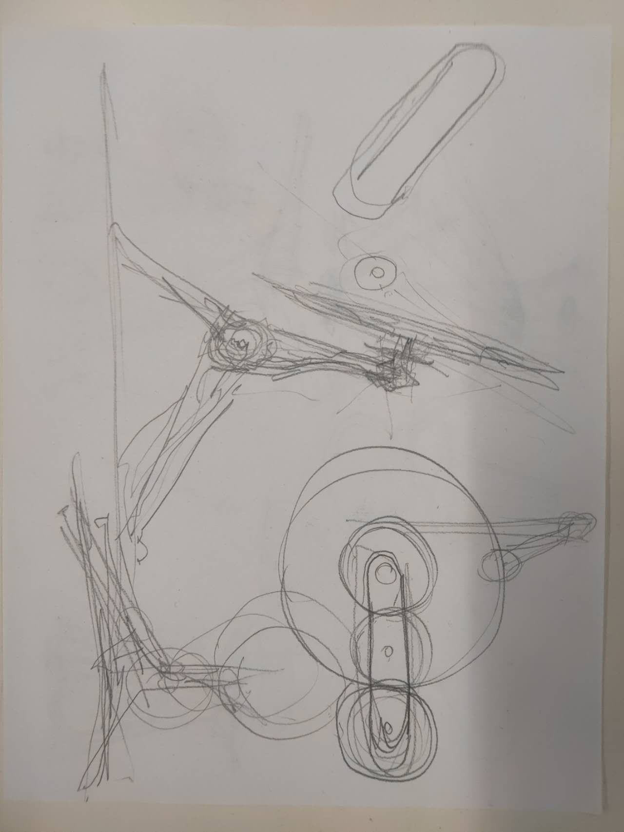
I first start with a sketch, with a gestural outline. There is a main gear which turns the whole thing and becomes the central attraction piece. The big gear will be turned by a smaller gear connected to a stepper motor, which is powerful enough for the task. The big gear will have to turn the smaller nodes and pull the paddle system at different intervals. The paddles are going to move in a sin curve.
I want to make a machine, a sculpture, with moving parts. So, the device could look impressive. The difficult part is how to make the device powered by simplistic power sources.
I start to get zoned in on this idea of a six paddle device with a main gear in the middle, which will have a bunch of gears turning and strings pulling the paddles up and down.
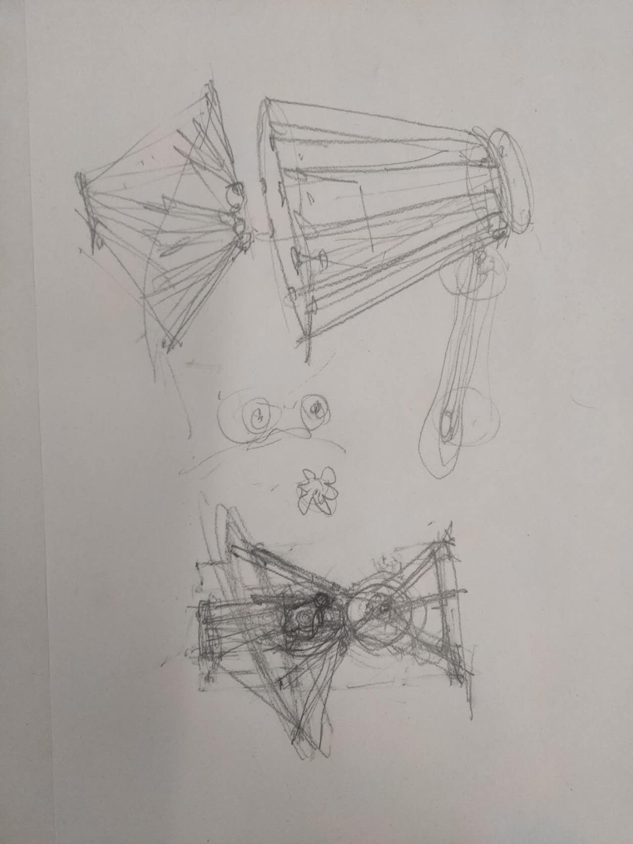
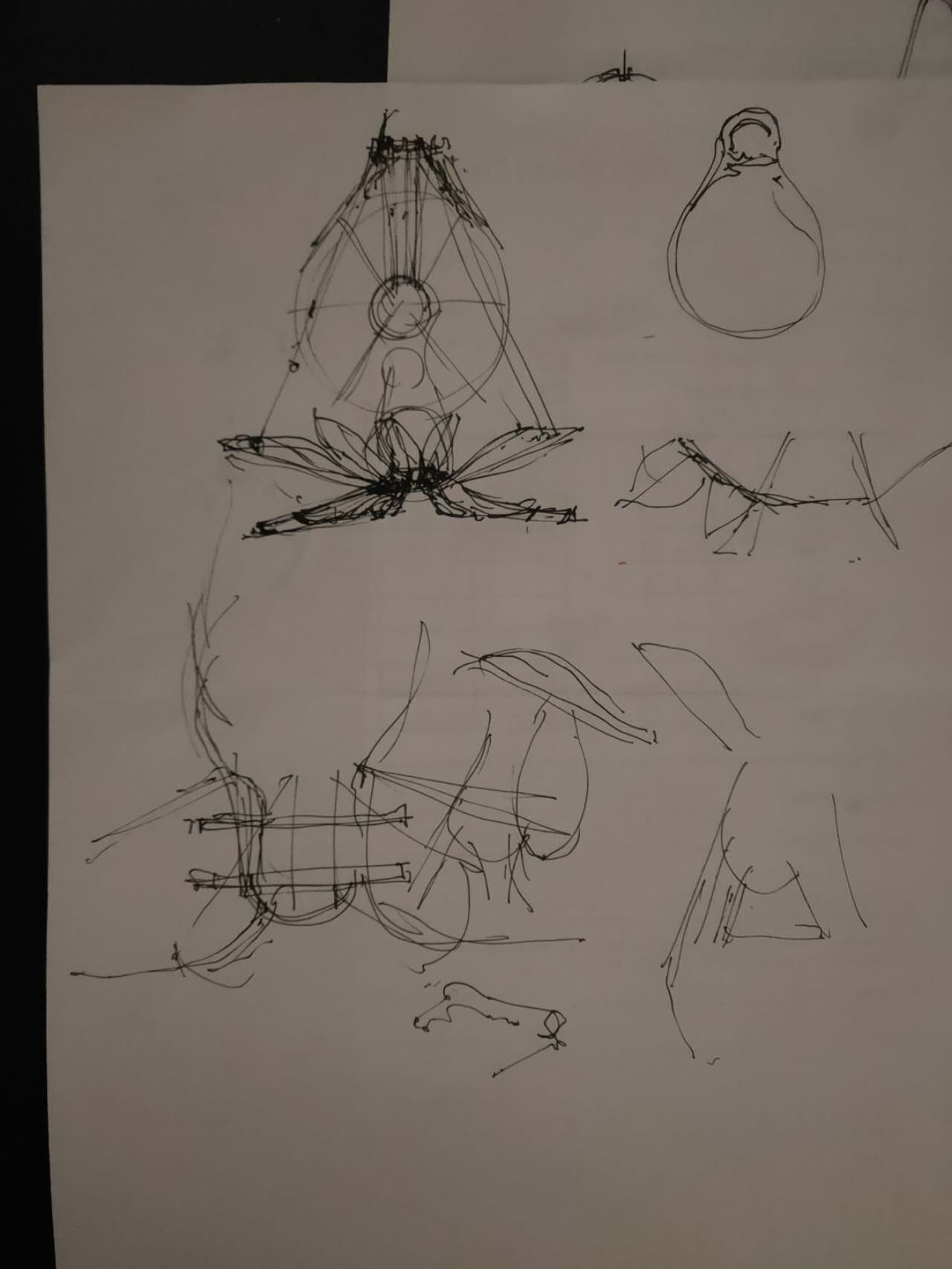
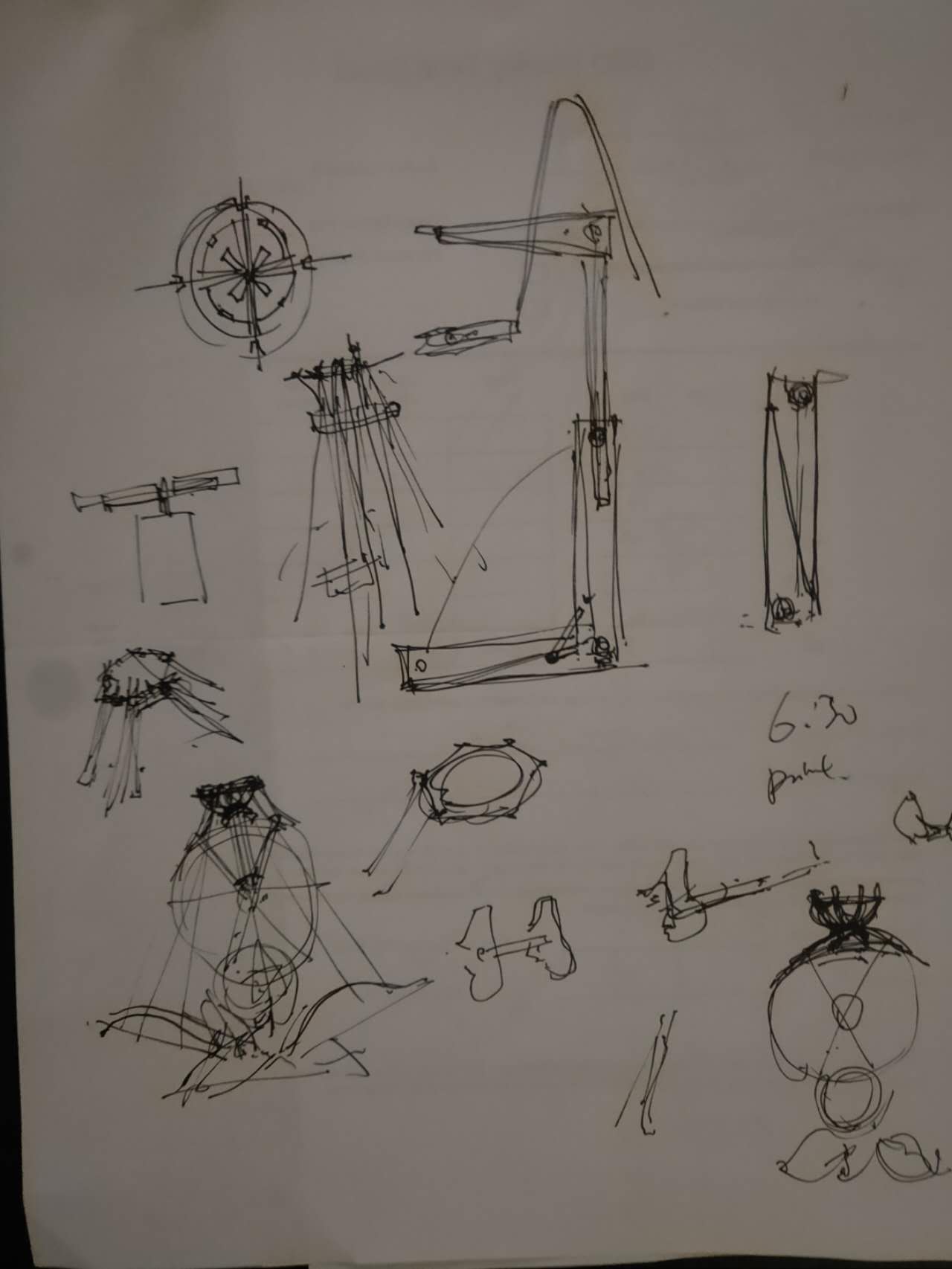
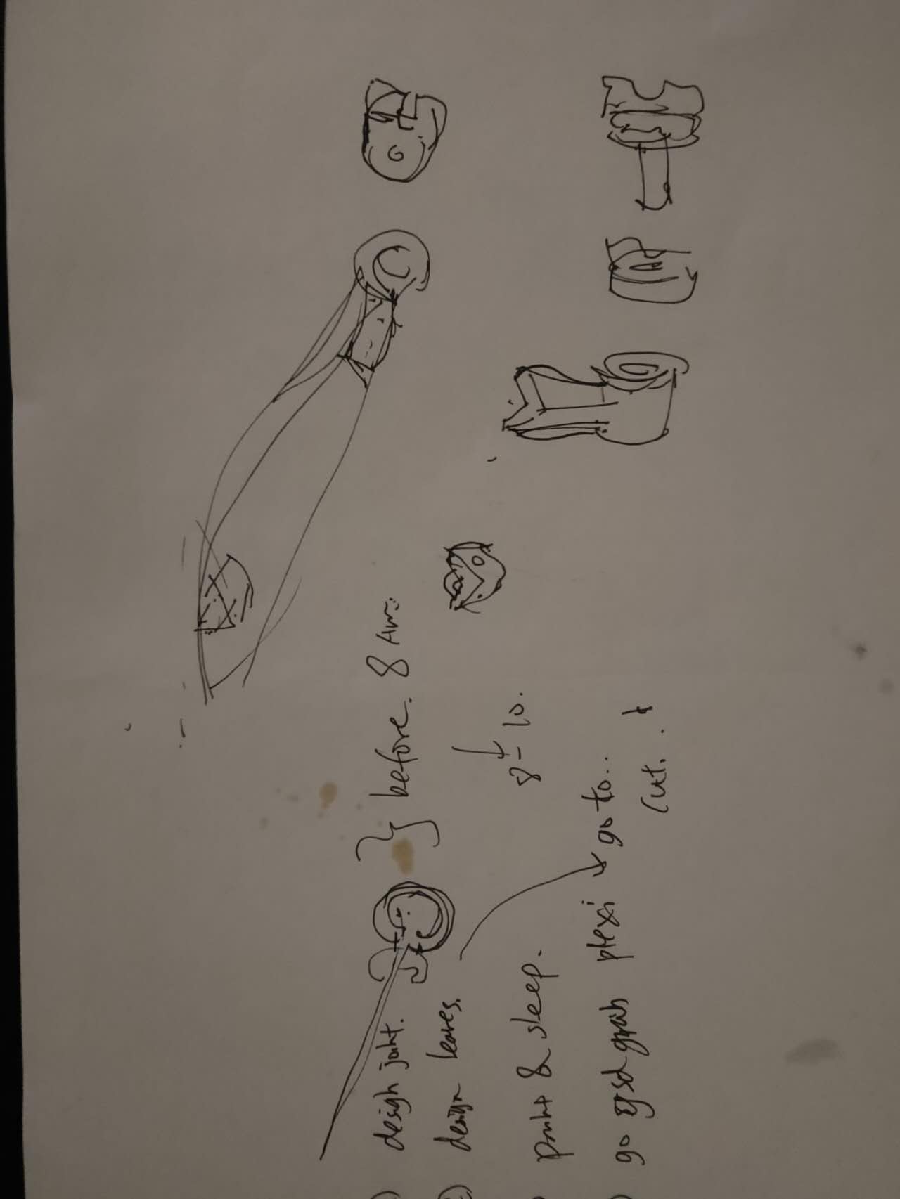
More sketches.
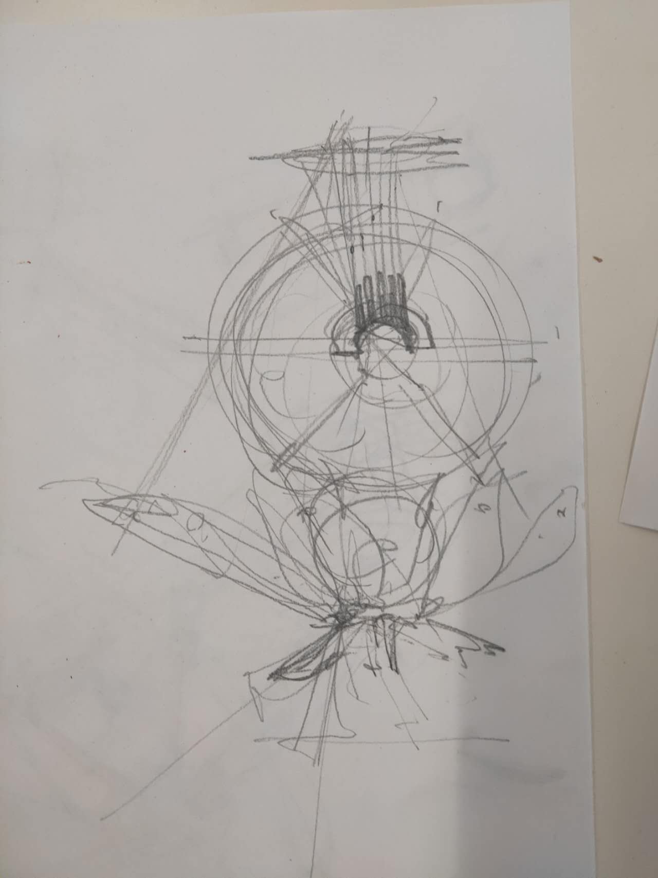
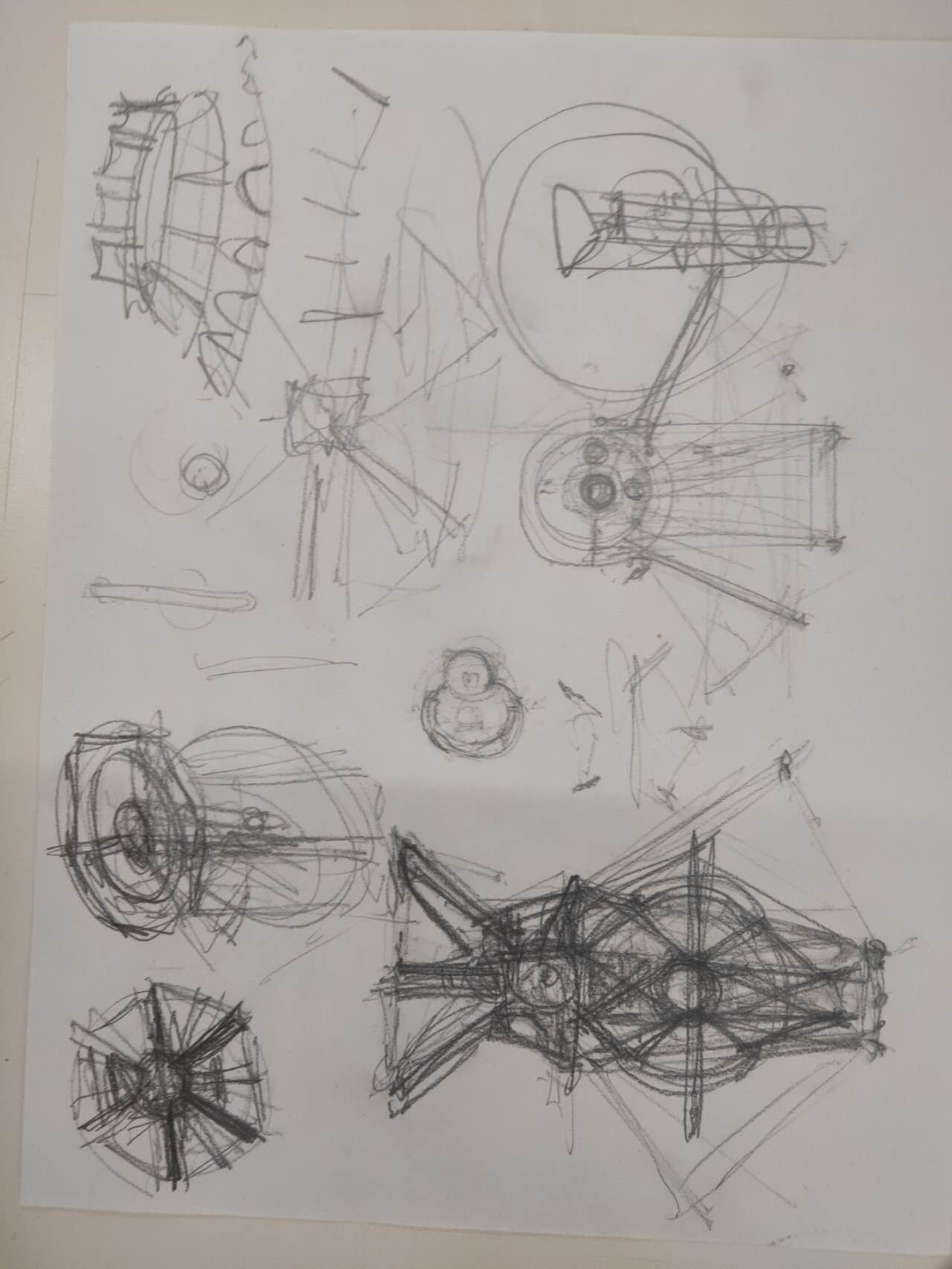
More sketches which has the general shape down.
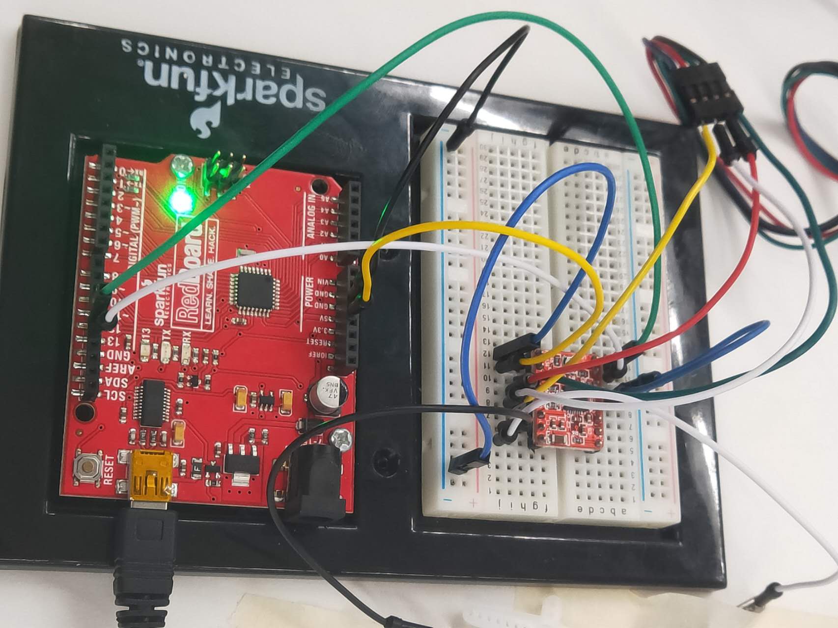
We did a quick proof of concept from an arduino code example online. It is allowing me to turn the motor with a existing driver module. I want to explain the specific details here. First I searched on google how to make a motor turn. In many websites I discovered I would need a driver board to connect to a "programmable microcontroller board" in order to act as a translator between the "programmable board" with the motor. The easy and accessible solution I've found is to use a A4988 Driver. You will find it in stock or on amazon. I've found two useful websites: last minute engineers' guide. How to Mechatronics' guide. To summarize: I would need to connect the motors to 4 pins on the driver (2B 2A and 1A 1B). The motor power supply will go to the driver's VMOT and GND. For my simple action I would connect reset pin to sleep pin (all on driver board), in order to override the sleep option for the stepper motor. Then, I would connect VDD pins and GND pins from the driver board to the microcontroller board. Finally, the most important step is to connect the drivers' two pin: Step pin and Direction pin, to the microcontroller. To summarize, I only need two digital pins on a SAMD board to make my final project work. Then, because of the pins I would need to turn a motor are so few (I only need two), I decide not to make a new board but rather just repurpose an old board which has two empty unused pins for my purpose for the final project. I dig through my boxes and found I've made a breakout breadboard on Week 7, following Quentin's SAMD21's pcb design. It is a complex board which allows all kind of programing to happen. He told us it is very future proof and we could use it in our final project (he actually said it). You can find his package here: download Quentin's board here .
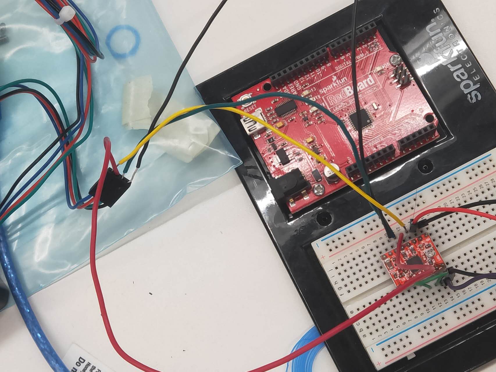
We quickly tested the connections on a breadboard. There are problems with the limiting switch, which opens more current to motor to allow the motor to turn. I got a philips head screwdriver and adjust the limitor to allow the motor to have the maximum power output, with a 12 V outlet attached.
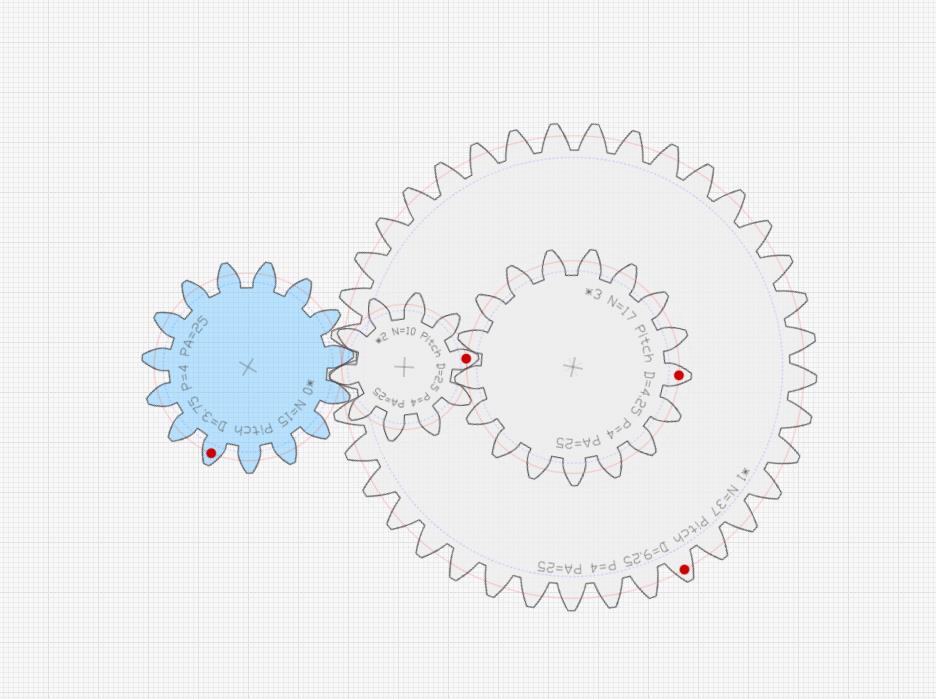
After I get the motor to turn successfully, I want to design the main drive gear which will power all the paddle pulleys. It was very tricky to get the the gears to work correctly. I opt to follow a template which will give me the most accurate turning motions.
I download the CAD outline from an online website (Search gears tenplate design on google and you will find multiple free websites.)
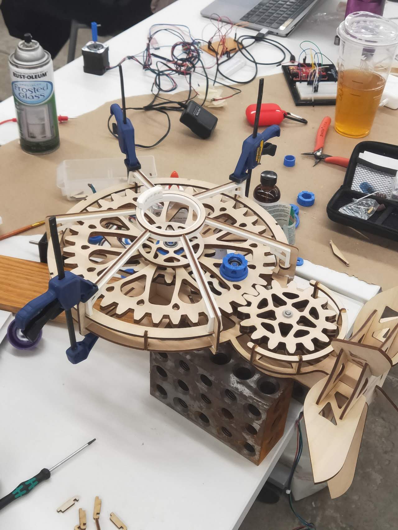
The gears are assembled together in Rhino, and they look quite nice together.
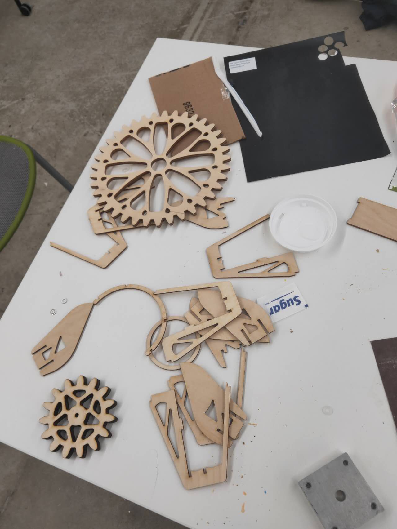
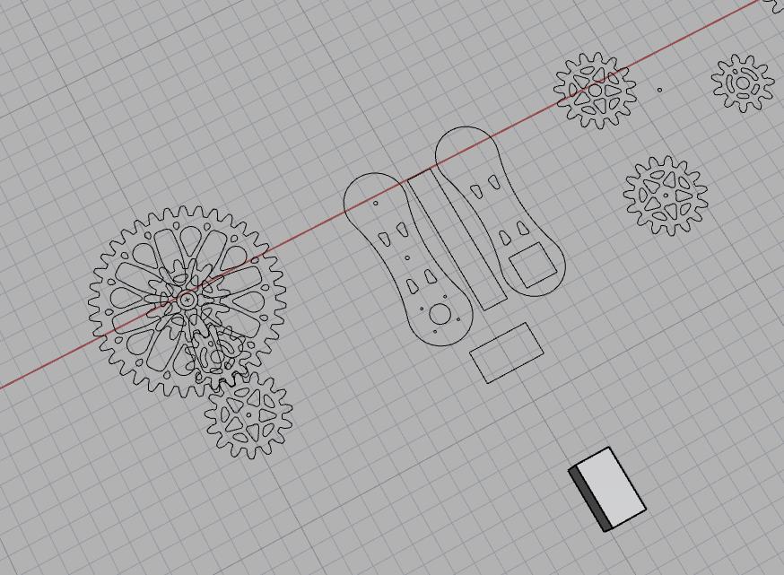
I start to laser cut some of the gears files, because the main gear have to work correctly.
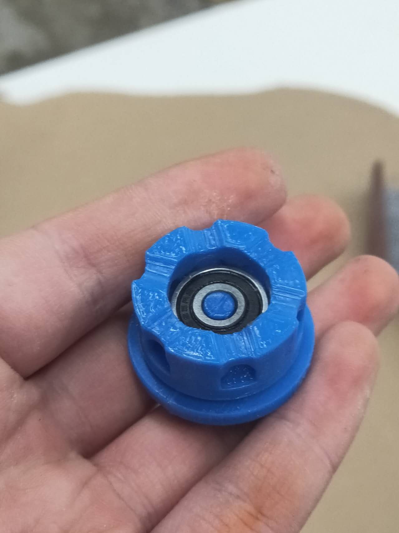
I 3d print a turning table to attach all the strings, all six of them, on the gear. I insert a ball bearing in the part so the string connected top half can rotate freely from the bottom half while staying connected.
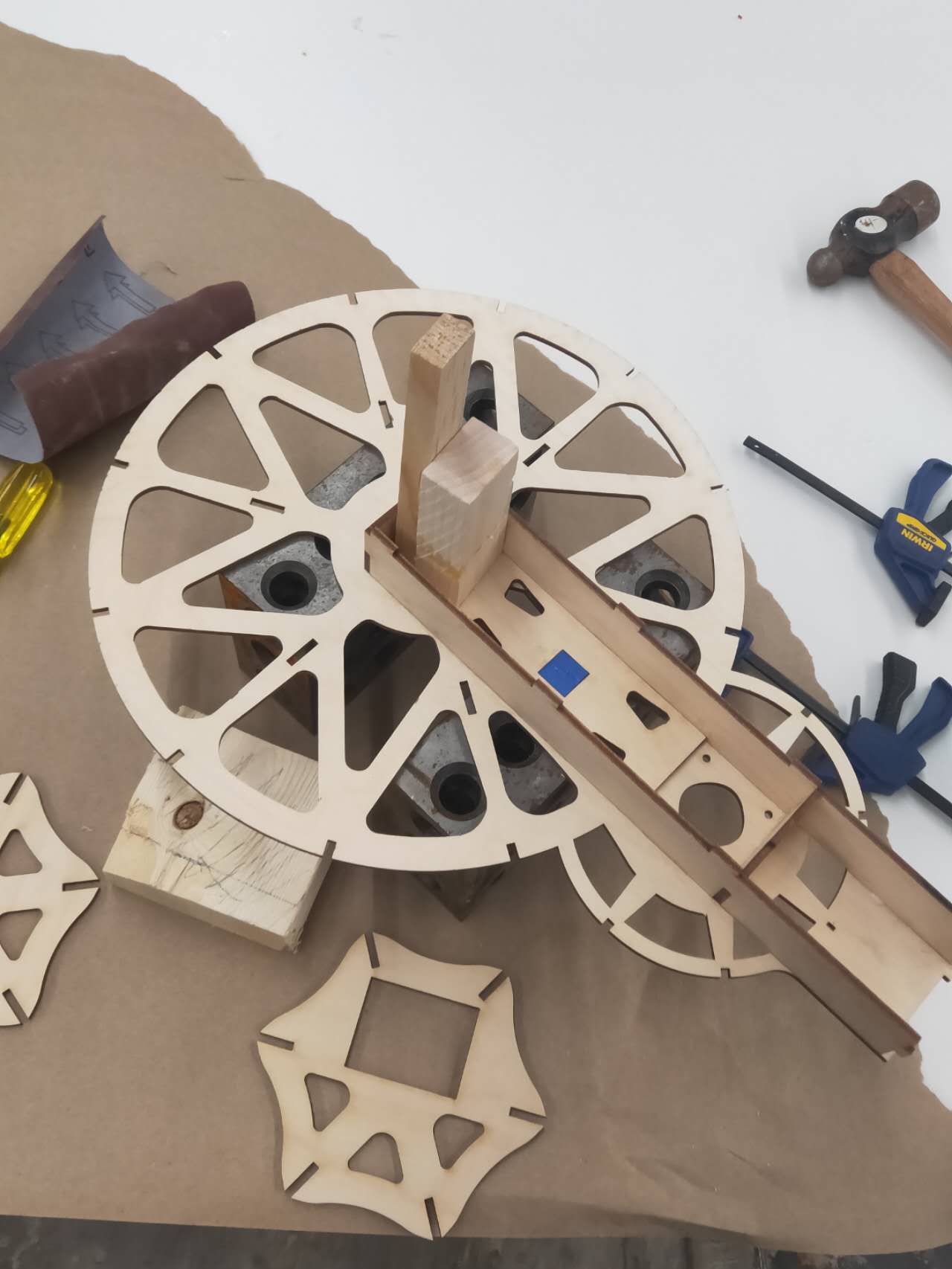
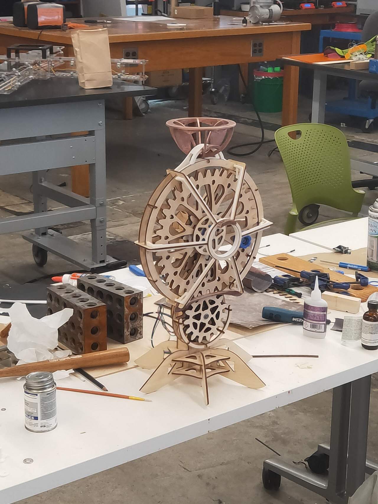
The maingear assembled
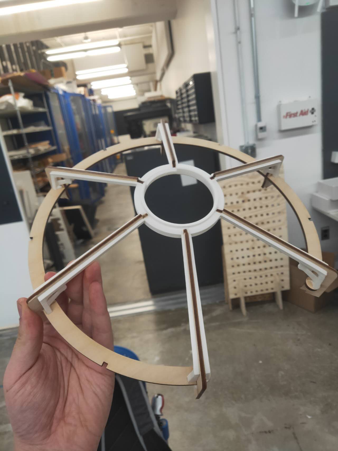
The maingear also has a cage cover which will be the structure and connection nodes.
I place the whole thing flat on table so I can adjust more things.
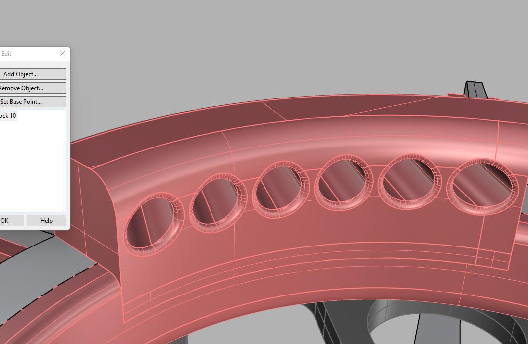
I designed a crown piece to add holes for more strings to go through. The whole structure becomes the tip of the umbrella.
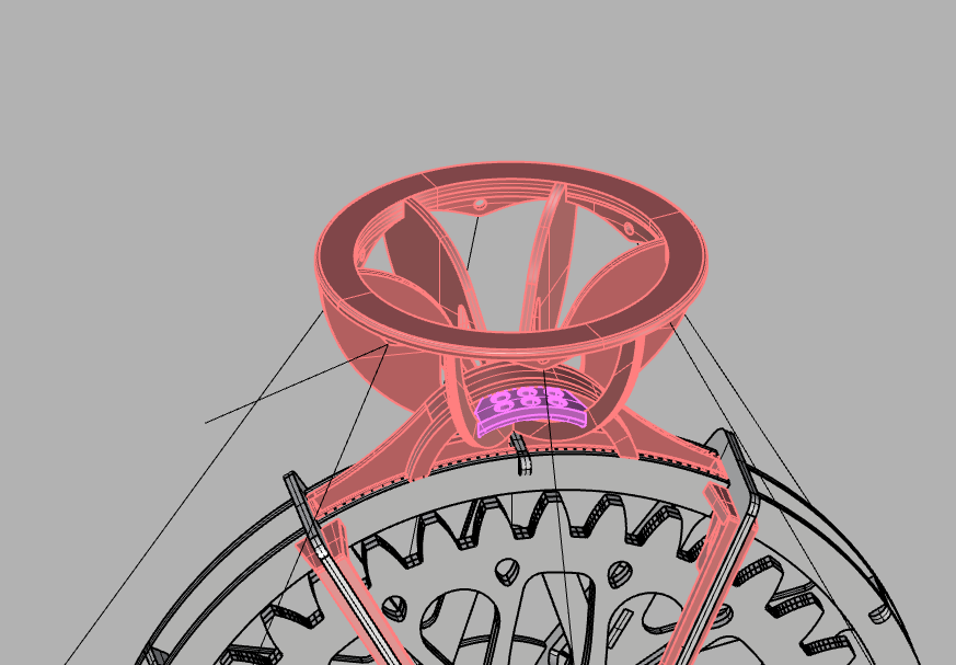
The crown piece will be in the general motif of the flower paddles
On the center of the main gear cover, I place a 3d printed piece for string arrangements.
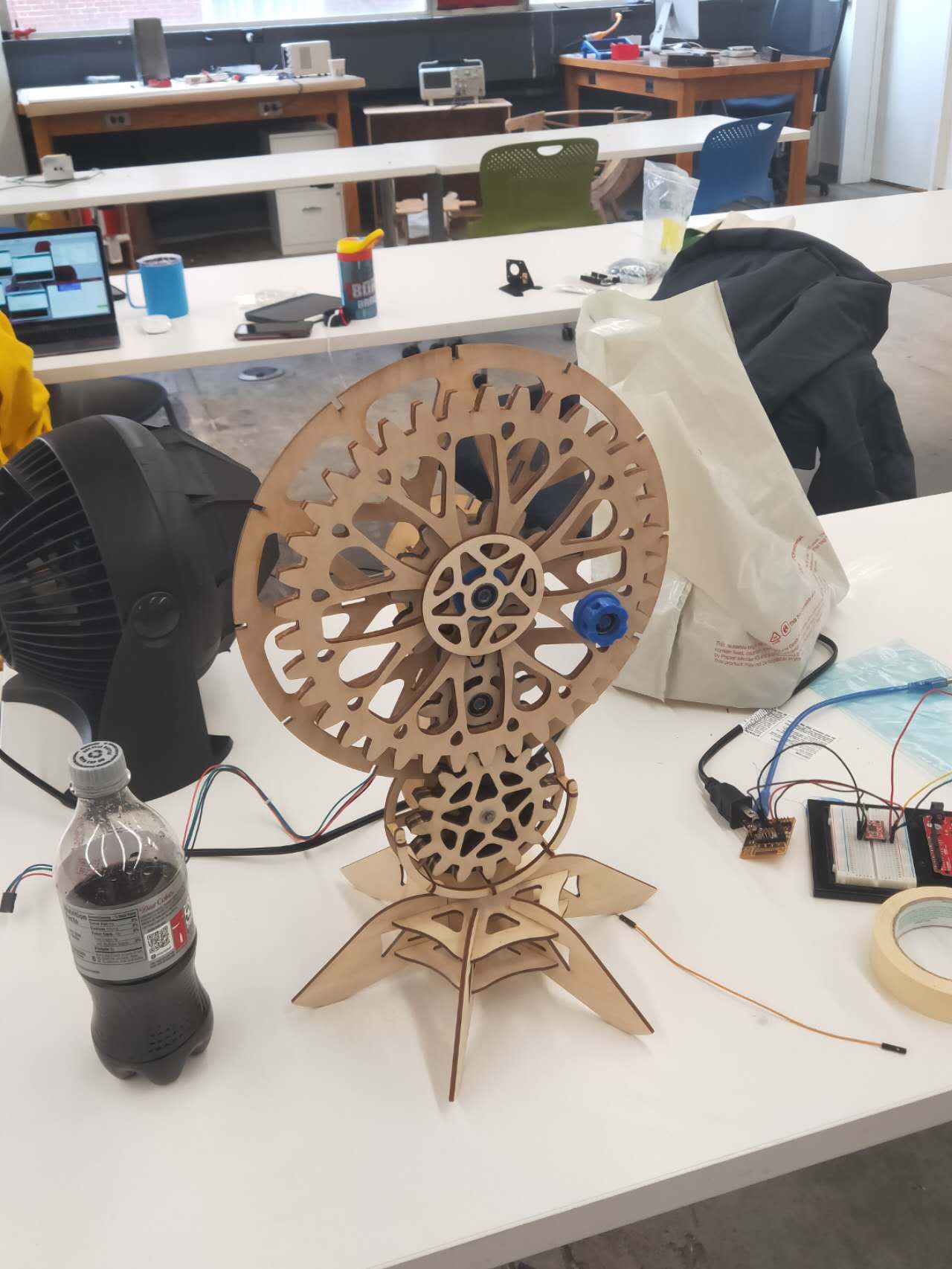
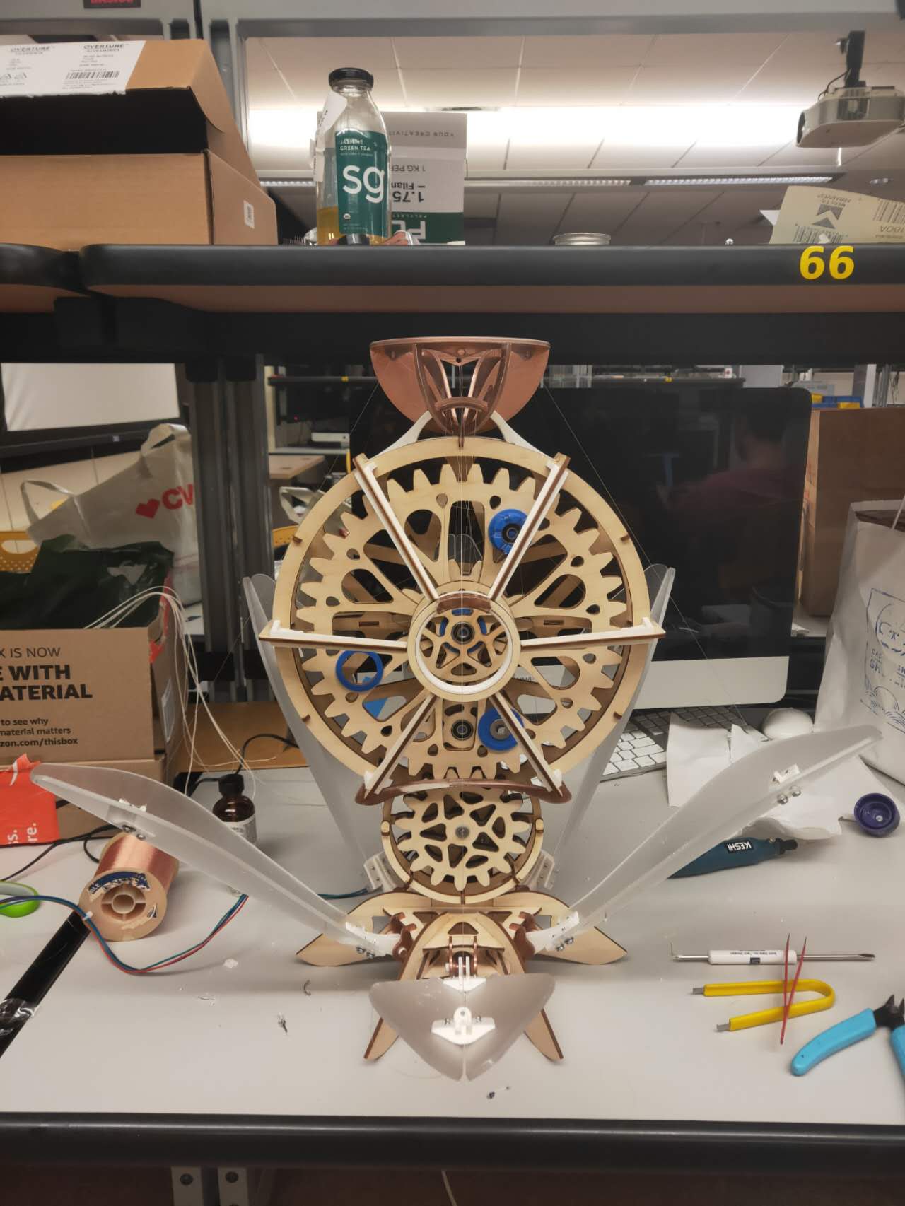
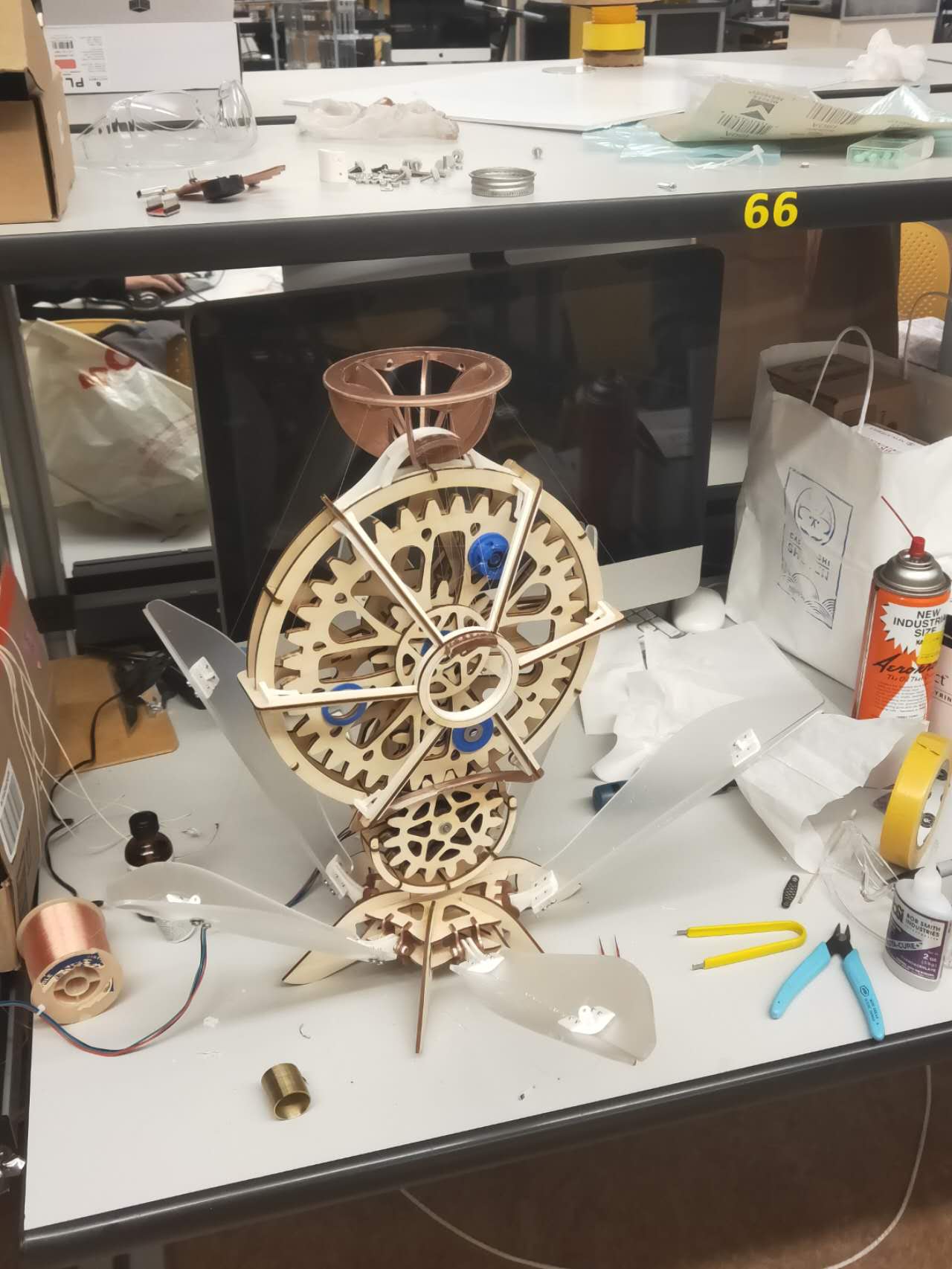
How it looks when all these parts are assembled
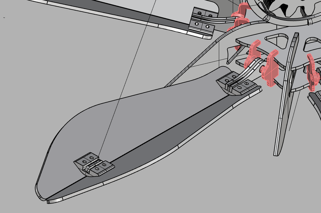
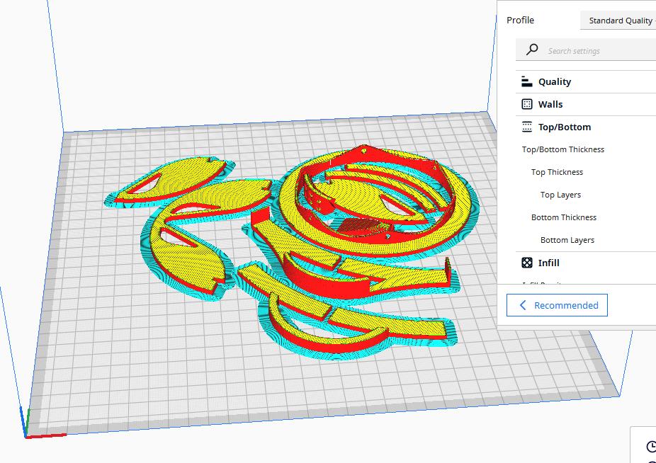
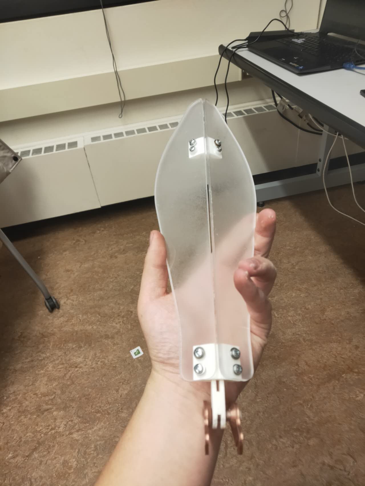
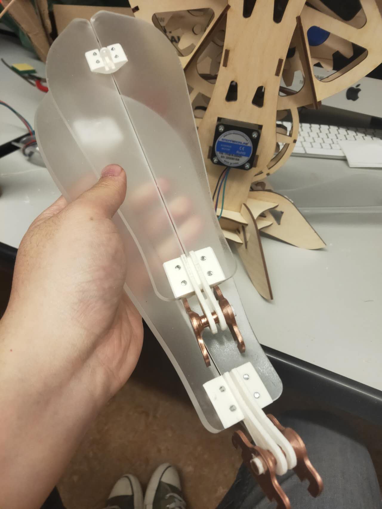
Finally, I designed a paddle piece for the final part of the flower machine. The paddles will be made out of lasercut plexi. Two pieces of them will be bolted on a piece of triangular 3d printed joint.
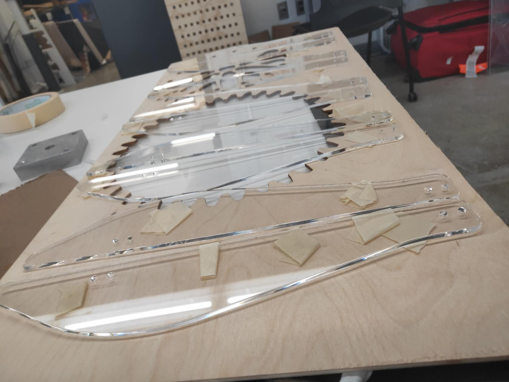
I laid out all the plexi cuts and sprayed matte spray paint on top of them. The matte spray paint will act like frosted spray, making the transparent plexi a bit more translucent.
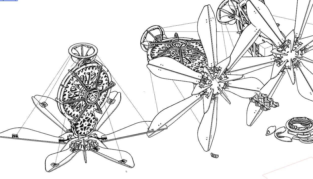
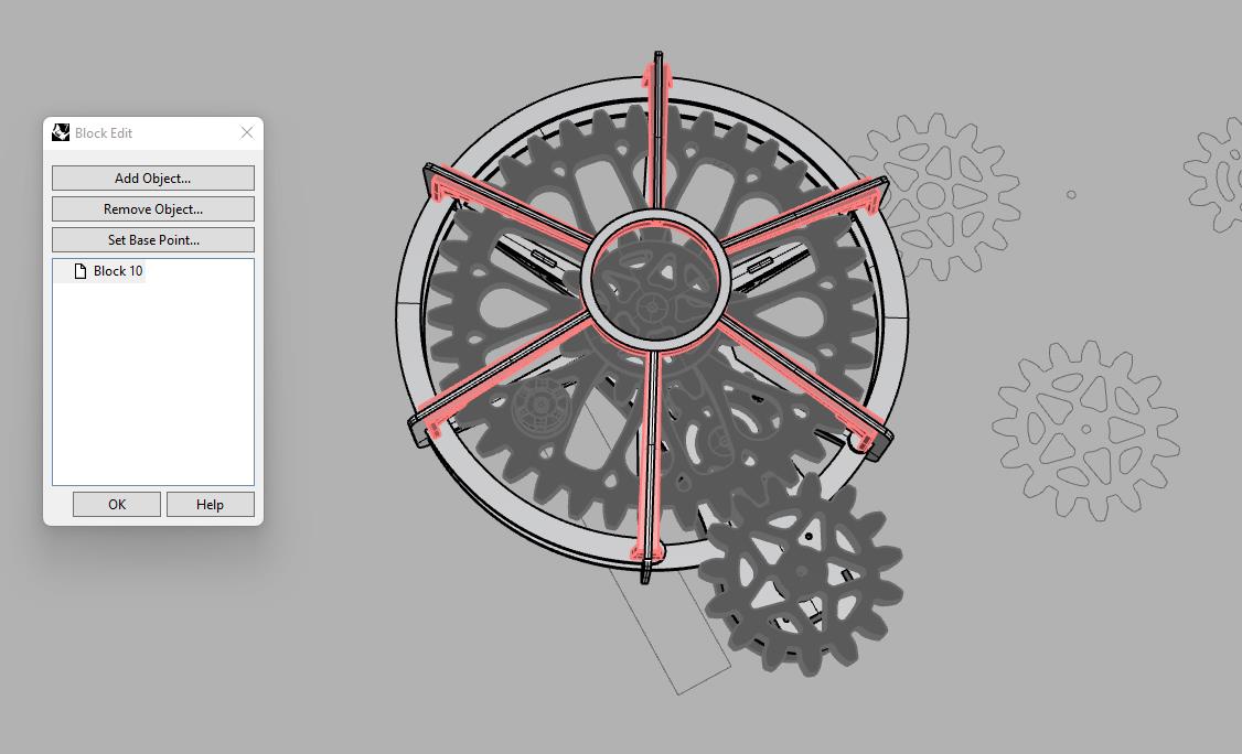
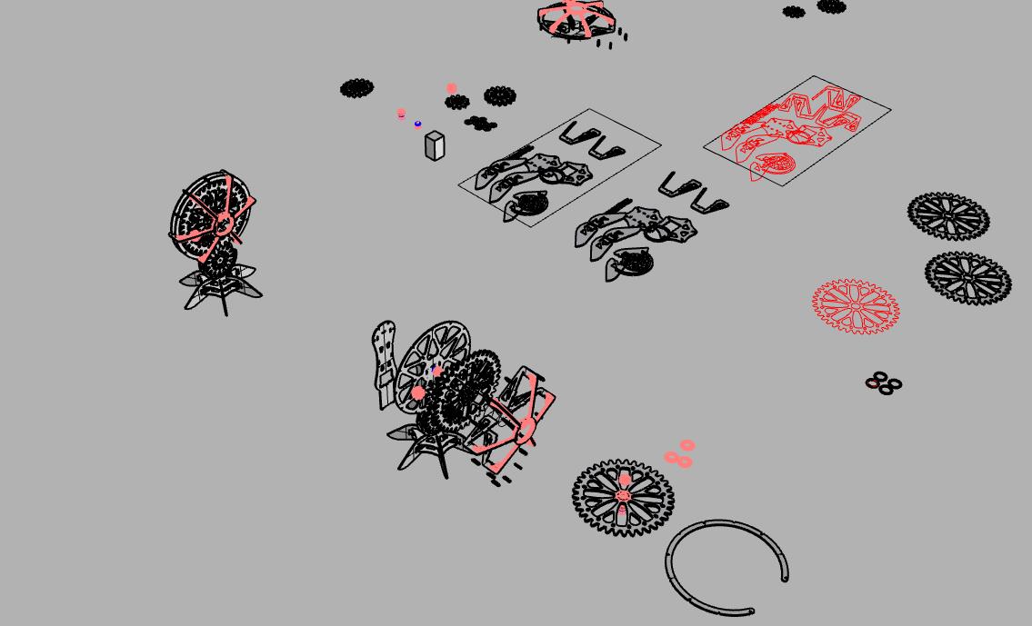
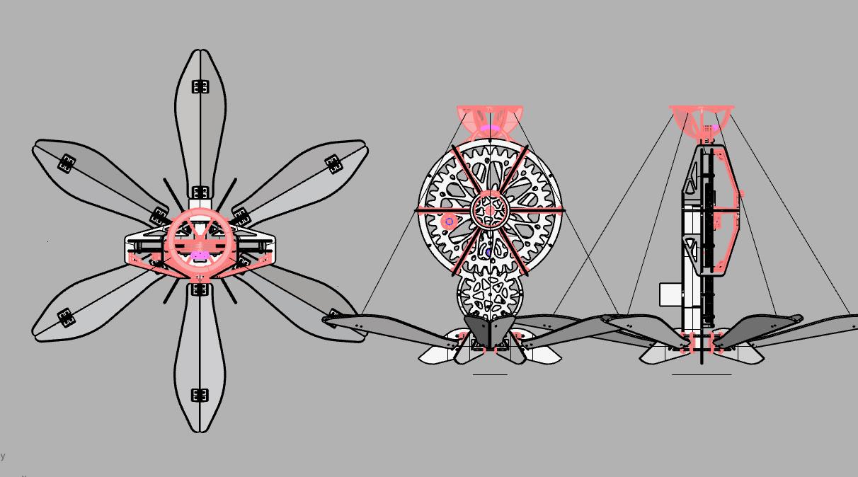
Over all 3d model for the whole device. I made the whole thing a block so I can make copies of them with different orientation. Thus, I can model in plan and sections.
It was quite troublesome to add all the strings. At first I added the cotton string, but the friction was so strong that it locks the entire mechanism. Eventually I replace the cotton string with fishing string. The fishing string is stronger, and more importantly, they are smoother. Hence, the string can pass through the hinge with less friction.
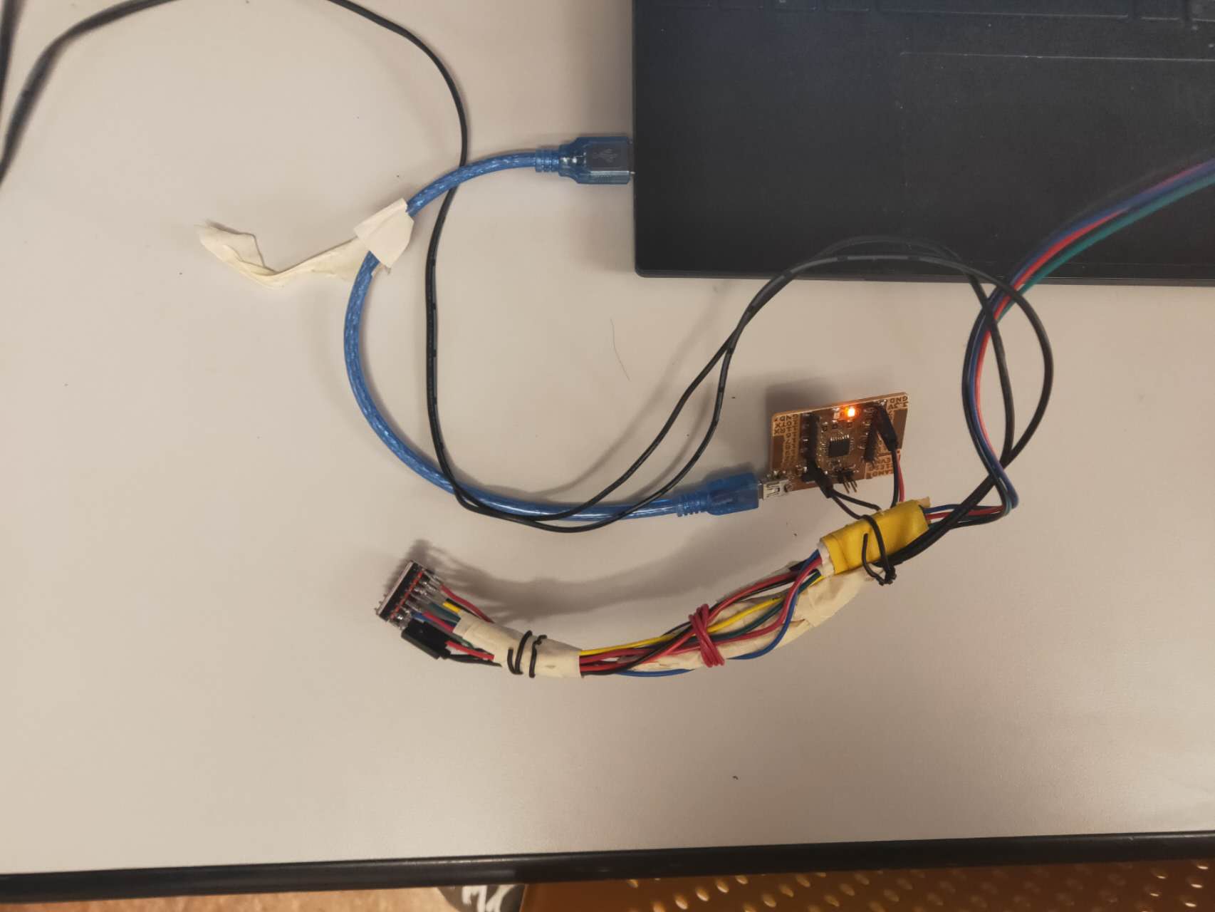
The input method for this device is using a driver and a regular SAMD21E for all the communication between the SAMD chip and the stepper motor.
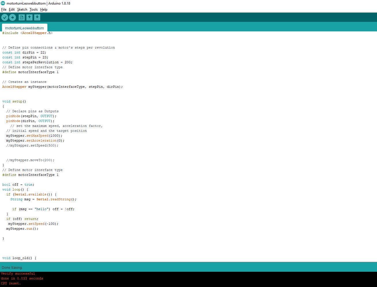
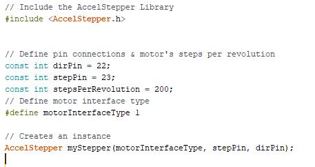
The code I wrote for the stepper motor is very simple. There is only one page of code. I installed the AccelStepper library and I can program the motor with much more ease.
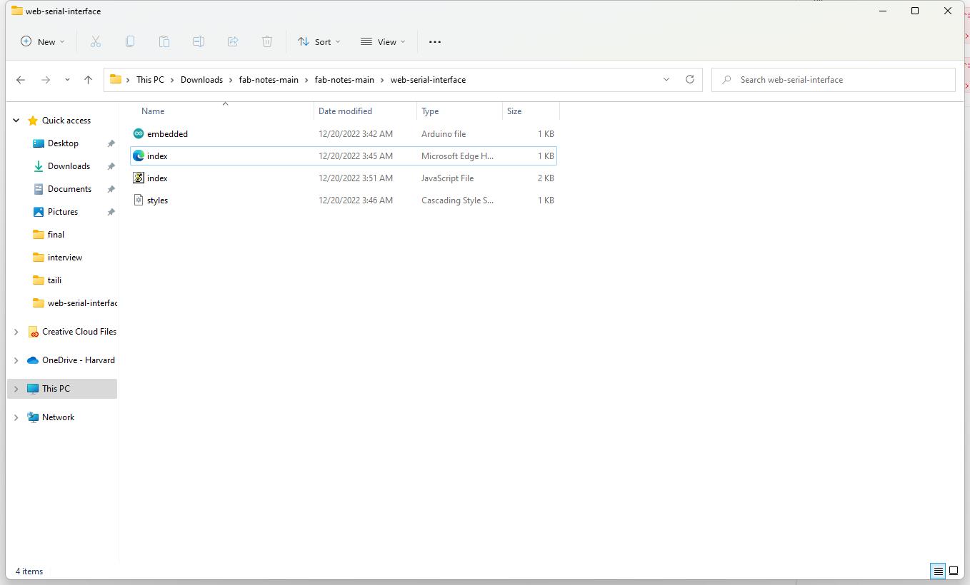
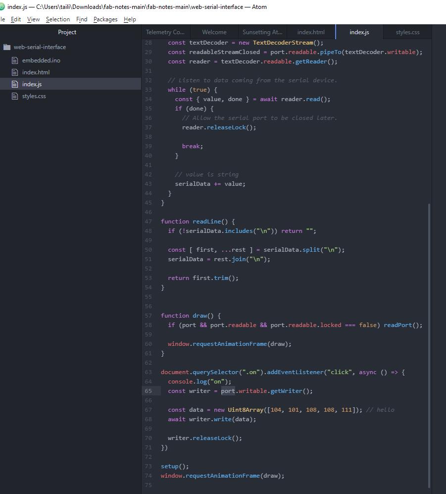
I also got help from Leo, who let me download his web socket package and Javascript code. With Atom, we made the arduino and Javascript to run at the same time. Through this, We can edit an html page to be a press bottom for my machine flower. We made a simple round red bottom. Upon pressing, the machine can be activated or closed down.
Here is the control interface for the bottom.

The video shows the mechanical lotus in motion.
Here are the files for my entire Clockwork lotus design.
Download Template Trace